
Page 7 - Osawa Update Catalogue 2019
P. 7
CUTTING PARAMETERS
HF871 M1 N1 M2 M3 N3 M4 N4
N2
S4
N1
P4
S2
N3
M1 M2 N2 P1 S1 M3 M4 N4 P2 P3 S3 M5 N5 M1 M4 N4 M2 M3 M5 N5
N1
N3
N2
Material Group P1 P2 M1 K1 H1 H1 P3 P4 M2 N2 K3 P5 M3 M4 P1 P4 S4 P2 P3 P5 S5
N1
H4 H4
S3
S2
S3
S2
S1
S4
S5
N3
K4
H2 H2H3 H3
K2
S1
N4
ISO 513
P3
H1 H1H2 H2
K1 K2 P1 S1 K3 H3 H3H4 H4 K5 H5 H5 K1 H1 H1H4 H4 K2 K3 K5
P4
S3
K4
P2
S2
K4
H2 H2H3 H3H5 H5
S4
Hardness/Rm ≤ 700 N/mm² 700-1000 N/mm² ≤ 35 HRC ≤ 40 HRC
H2 H2
K1
K2
H3 H3H4 H4
K4
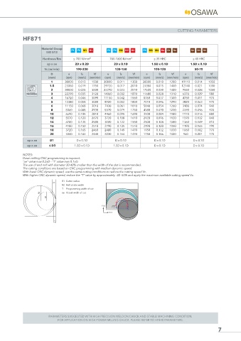
ap x ae 2D x 0.2D H1 H1 2D x 0.1D K3 1.5D x 0.1D 1.5D x 0.1D
Vc (m/min) 190-230 130-150 100-120 50-70
D n fz Vf n fz Vf n fz Vf n fz Vf
(mm) (rpm) (mm/z) (mm/min) (rpm) (mm/z) (mm/min) (rpm) (mm/z) (mm/min) (rpm) (mm/z) (mm/min)
1 30000 0.013 1500 30000 0.011 1350 30000 0.010 1200 19110 0.014 1050
1.5 23350 0.019 1750 29720 0.017 2010 23350 0.015 1400 12740 0.021 1050
2 30000 0.025 3000 22290 0.023 2010 17520 0.020 1400 9550 0.028 1050
TROCHOIDAL 3 22290 0.035 3120 14860 0.032 1870 11680 0.028 1310 6370 0.039 980
4 16720 0.046 3090 11150 0.042 1860 8760 0.037 1300 4780 0.051 970
5 13380 0.058 3080 8920 0.052 1850 7010 0.046 1290 3820 0.063 970
6 11150 0.068 3010 7430 0.061 1810 5840 0.054 1260 3180 0.074 940
8 8360 0.088 2930 5570 0.079 1750 4380 0.070 1230 2390 0.096 920
10 6690 0.105 2810 4460 0.095 1690 3500 0.084 1180 1910 0.116 880
12 5570 0.120 2670 3720 0.108 1610 2920 0.096 1120 1590 0.132 840
14 4780 0.135 2580 3180 0.122 1550 2500 0.108 1080 1360 0.149 810
16 4180 0.150 2510 2790 0.135 1510 2190 0.120 1050 1190 0.165 790
18 3720 0.165 2460 2480 0.149 1470 1950 0.132 1030 1060 0.182 770
20 3340 0.183 2440 2230 0.164 1470 1750 0.146 1020 960 0.201 770
ap x ae D1 D x 0.1D D x 0.1D D x 0.1D D x 0.1D
ap x ae ≤ D3 1.5D x 0.1D 1.5D x 0.1D D x 0.1D D x 0.1D
NOTES:
Down milling CNC programming is required.
“ae” value max 0.2xD - “T” value max 0.1xD.
The use of end mill with diameter 30-40% smaller than the width of the slot is recommended.
The cutting conditions are based on CNC programming with medium dynamic speed.
With lower CNC dynamic speed, use the same cutting conditions or reduce the cutting speed Vc.
With higher CNC dynamic speed, reduce the “T” value by approximately -30 -50% and apply the maximum available cutting speed Vc.
R1 Cutter radius
ae
R2 Half of slot width
T Programming width of cut
R2 ae Actual width of cut
R1
Y (+)
Y
X (+)
T
PARAMETERS SUGGESTED WITH HIGH PRECISION WELDON CHUCK AND STABLE MACHINING CONDITION.
FOR APPLICATION ON HIGH POWER MILLING CHUCK, PLEASE REFER TO HF840 PARAMETERS.
7